Menu ini berisi cuplikan bukunya :
Automation, Production System, And Computer-Integrated Manufacturing
by Mikell P. Groover
1987
part I Fundamentals of Manufacturing and Automation
Menu ini berisi cuplikan bukunya :
Automation, Production System, And Computer-Integrated Manufacturing
by Mikell P. Groover
1987
part I Fundamentals of Manufacturing and Automation
In this section we present some of the fundamental principles of computer-assisted part programming using APT. The reader will certainly not become an expert part programmer after completing this introduction. Our objectives are much less ambitious. What we hope to accomplish is merely to demonstrate the English-like statements of AFT and to show how they can be formulated to command the cutting tool through its sequence of machining operations.
APT is not only an NC language; it is also the computer program that performs the calculations to generate cutter positions based on APT statements. We will not concern ourselves with the internal workings of the computer program. Instead, we will concentrate on the language that the part programmer must use.
APT is a three dimensional system that can be used to control up to five axes. We will limit our discussion to the more familiar three axes, x, y, and z, and exclude rotational coordinates. APT can be used to control a variety of different machining operations. We will cover only drilling and milling applications. There are over 400 words in the AN vocabulary. Only a small (but important) fraction will be covered here.
To program in APT, the work part geometry must first be defined. Then the tool is directed to various point locations and along surfaces of the work part to carry out the machining operations. The viewpoint of the part programmer is that the workpiece remains stationary and the tool is instructed to move relative to the part.
There are four types of statements in the AFT language:
1. Geometry statements. These define the geometric elements that comprise the work part. They are also sometimes called definition statements.
2. Motion statements. These are used to describe the path taken by the cutting tool.
3. Post processor statements. These apply to the specific machine tool and control system. They are used to specify feeds and speeds and to actuate other features of the machine.
4. Auxiliary statements These are miscellaneous statements used to identify the part, tool, tolerances, and so on.
Geometry statements
When the tool motions are specified, their description is in terms of points and surfaces. Therefore, the points and surfaces must be defined before tool motion commands can be given.
The general form of an APT geometry statement is this :
symbol = geometry ty/descriptive data (9.1)
An example of such a statement is
P1 = POINT/5.0, 4.0, 0.0 (9.2)![]()
The statement is made up of three sections. The first is the symbol used to identify the geometric element. A symbol can be any combination of six or fewer alphabetic and numeric characters. At least one of the six must be an alphabetic character. Also, although it may seem obvious, the symbol cannot be one of the APT vocabulary words.Some examples may help to show what is permissible as a symbol, and what is not permissible :
PZL Permissible
PABCDE Permissible
PABCDEF No; too many characters
123789 No; must have alphabetic character
POINT No; APT vocabulary word
P1.2 No; only alphabetic and numeric characters are allowed
The second section of the geometry statement is an APT vocabulary wort that identifies the type of geometry element. Besides POINT, other geometry elements in the APT vocabulary include LINE, PLANE, and CIRCLE.
The work part of Example 9.2 was relatively simple, it was a suitable application for manual programming. Most parts machined on NC systems are considerably more complex. In the more complicated point-to-point jobs and in contouring applications, manual part programming becomes an extremely tedious task and subject to error. In these instances it is much more appropriate to employ the high-speed digital computer to assist in the part programming process. Many part programming language systems have been developed to automatically perform most of the calculations which the programmer would otherwise be forced to do. This saves time and results in a more accurate and more efficient part program.
The part programmer’s job
The difference in the part programmer’s job between manual programming and computer-assisted programming is this. With manual programming, a manuscript is used which is formatted so that the NC tape can be typed directly from it. With computer-assisted part programming, the machining instructions are written in English-like statements of the NC programming language, which are then processed by the computer to prepare the tape. The computer automatically punches the tape in the proper tape format for the particular NC machine.
When utilizing one of the NC programming languages, part programming can be summarized as consisting basically of two tasks :
1. Defining the geometry of the work part
2. Specifying the tool path and/or operation sequence
Let us now consider these two tasks in computer-assisted part programming. Our frame of reference will be for a contouring application, but the concepts apply for a positioning application as well.
 WORKPART GEOMETRY DEFINITION. No matter how complicated the work part may appear, it is composed of basic geometric elements. Using a relatively simple work part to illustrate, consider the component shown in Figure 9.7. Although somewhat irregular in overall appearance, the outline of the part consists of intersecting straight lines and a partial circle. The holes in the part can be expressed in terms of the center location and radius of the hole. Nearly any component that can be conceived by a designer can be described by points, straight lines, planes, circles, cylinders, and other mathematically defined surfaces. It is the part programmer’s task to enumerate the component elements out of which the work part is formed. Each geometric element must be identified and the dimensions and location of the element explicitly defined. Using the APT programming language as an example, the following statement might be used to define a point :
P1 – POINT/6.0, 1.125,0
The point is identified by the symbol P1 and is located at x = 6.0, y = 1.125, and z = 0.
Similarly, a circle in the x–y plane might be defined by the APT statement
C1 = CIRCLE/CENTER, P1 , RADIUS, 1.12
The center of circle C1 is Pi (previously defined) and the radius is 1.125.
The various geometric elements in the drawing of Figure 9.7 would be identified in a similar fashion by the part programmer.
TOOL PATH CONSTRUCTION After defining the work part geometry, the programmer must next construct the path that the cutter will follow to machine the part. This tool path specification involves a detailed step-by-step sequence of cutter moves. The moves are made along the geometry elements which have previously been defined. To illustrate, using Figure 9.7 and the APT language, the following statement could be used to command the tool to make a left turn from line L2 onto line L3 :
GOLFT/L3, PAST, L1
This assumes the tool was previously located at the intersection of lines L2 and L3 and had just finished a cut along L2. The statement directs the tool to cut along L3 until it just passes line L1.
By using statements similar to the above, the tool can be directed to machine along the work part surfaces, to go to point locations, to drill holes at those point locations, and so on. In addition to geometry definition and tool path specification, the part programmer also provides other commands to the NC system. However, let us await Section 9.5, where we will consider a wide range of possible APT statements.
The computer’s job
The computer’s job in computer-assisted part programming consists of the following steps:
1. Input translation
2. Arithmetic calculations
3. Cutter offset computation
4. Post processor
The sequence of these steps and their relationships to the part programmer and the machine tool are illustrated in Figure 9.8.
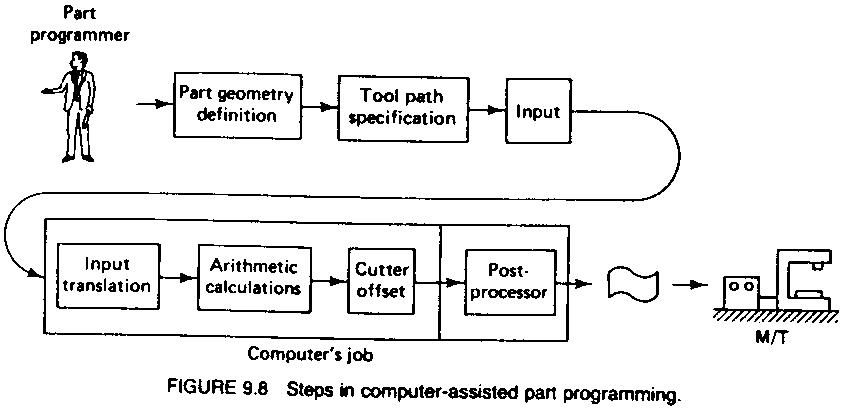 INPUT TRANSLATION. The part programmer enters the program using the APT or other language. The input translation component converts the coded instructions contained in the program into computer-usable form, preparatory to further processing.
ARITHMETIC CALCULATIONS. The arithmetic calculations unit of the system consists of a comprehensive set of subroutines for solving the mathematics required to generate the part surface. These subroutines are called by the various part programming language statements. The arithmetic unit is really the fundamental element in the part programming package. This unit frees the programmer from the time-consuming geometry and trigonometry calculations to concentrate on the work part processing.
CUTTER OFFSET COMPUTATION. When we described the second task of the part programmer as that of constructing the tool path, we ignored one basic factor the size of the cutting tool. The actual tool path is different from the part outline. I is is because the tool path is the path taken by the center of the cutter. It is at the periphery of the cutter that machining takes place.
The purpose of the cutter offset computation is to offset the tool path from the desired part surface by the radius of the cutter. This means that the part programmer can define the exact part outline in his geometry statements. Thanks to the cutter offset calculation provided by the programming system, he need not concern himself with this task. The cutter offset problem is illustrated in Figure 9.9.
POSTPROCESSOR. As we have noted previously, NC machine tool systems are different. They have different features and capabilities. They use different NC tape formats. Nearly all of the part programming languages, including APT, are designed to be general-purpose languages, not limited to one or two machine tool types. Therefore, the final task of the computer in computer-assisted part programming is to take the general instructions and make them specific to a particular machine tool system. The unit that performs this task is called a post processor.
The post processor is really a separate computer program that has been written to prepare the punched tape for a specific machine tool. The input to the post processor is the output from the other three components: a series of cutter locations and other instructions. This is referred to as the CLFILE or CLDATA (CL stands for cutter location). The output of the post processor is the NC tape written in the correct format for the machine on which it is to be used.
NC part programming languages
Probably over 100 NC part programming languages have been developed since the initial MIT research on NC programming systems in 1956. Most of the languages were developed to serve particular needs and machines and have not survived the test of time. However, a good number of languages are still in use today. In this subsection we review some of those which are generally considered important.
 APT (AUTOMATICALLY PROGRAMMED TOOLS). The API language was the product of the MIT developmental work on NC programming systems. Its development began in June 1956, and it was first used in production around 1959. Today it is the most widely used language in the United States. Although first intended as a contouring language, modern versions of APT can be used for both positioning and continuous-path programming and continuous-path programming in up to five axes.
AUTOSPOT (AUTOMATIC SYSTEM FOR POSITIONNING TOOLS). This was developed by IBM and first introduced in 1962 for PTP programming. Today’s version of AUTOSPOT can be used for contouring as well.
SPLIT (SUNDSTRAND PROCESSING LANGUAGE INTERNALLY TRANSLATED). This is a proprietary system intended for Sundstrand’s machine tools. It can handle up to five axis positioning and possesses contouring capability as well. One of the unusual features of SPLIT is that the post processor is built into the program. Each machine tool uses its own SPLIT package, thus obviating the need for a special post processor.
COMPACT II. This is a package available from Manufacturing Data Systems, Inc. (MDSI), a firm based in Ann Arbor, Michigan. The NC language is similar to SPLIT in many of its features. MDSI leases the COMPACT II system to its users on a time-sharing basis. The part programmer uses a remote terminal to feed the program into one of the MDSI computers, which in tum produces the NC tape.
ADAPT (ADAPTATION OF APT). Several part programming languages are based directly on the APT program One of these is ADAPT, which was developed by IBM under Air Force contract. It was intended to provide many of the features of AFT but to utilize a significantly smaller computer. ADAPT is not as powerful as APT, but can be used to program for both positioning and contouring jobs.
EXAPT (EXENDED SUBSET OF APT). This was developed in Germany starting around 1964 and is based on the APT language. Itere are three versions: EXAPT I designed for positioning (drilling and also straight-cut milling), EXAPT ll designed for turning, and EXAPT III designed for limited contouring operations. One of the important features of EXAPT is that it attempts to compute optimum feeds and speeds automatically.
In manual programming, the part programmer specifies the machining instructions on a form called a manuscript. Manuscripts come in various forms, depending on the machine tool and tape format to be used. For example, the manuscript form for a two-axis point-to-point drilling machine would be different than one for a three-axis contouring machine. Three representative manuscript forms are illustrated in Figure 9.3. As mentioned, the manuscript is a listing of the relative tool and workpiece locations. It also includes other data, such as preparatory commands, miscellaneous instructions, and speed/feed specifications, all of which are needed to operate the machine under tape control. The manuscript is designed so that the NC tape can be typed directly from it on a Flexowriter or similar tape-punch device.
We shall divide manual programming jobs into two categories : point-to-point jobs and contouring jobs. Except for complex work parts with many holes to be drilled, manual programming is ideally suited for point-to-point applications. On the other hand, except for the simplest milling and turning jobs, manual programming can become quite time-consuming for applications requiring continuous-path control of the tool. Accordingly, we shall only concern ourselves with manual part programming for point-to-point operations in this chapter. Manual contour programming requires such tedious and detailed calculations that the space needed for the topic would be more than is warranted by the basic purpose of this book, which is to survey the field of automated manufacturing systems. Contouring is much more appropriate for computer-assisted part programming (Sections 9.4 and 9.5).
The basic method of manual part programming for a point-to-point application is best demonstrated by means of an example.
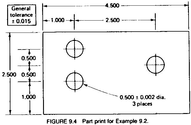
EXAMPLE 9.2
Suppose that the part to be programmed is a drilling job. The engineering drawing for the part is presented in Figure 9.4. Three holes are to be drilled at a diameter of 31/64 in. The close hole size tolerance requires reaming to 0.500 in. diameter. Recommended speeds and feeds are given[1] as follows
dia Speed (ft/min) Feed (in./rev)
0.484-in.-diameter drill 75 0.006
0.500-in.-diameter reamer 50 0.010
The NC drill press uses the tab sequential tape format. Drill bits are manually changed by the machine operator, but speeds and feeds must be programmed on the tape. The machine has the floating-zero feature and absolute positioning.
[1] Recommended cutting speeds and feeds could be obtained from machinability data handbooks
The first step in preparing the part program is to define the axis coordinates in relation to the work part. We assume that the outline of the part has already been machined before the drilling operation. Therefore, the operator can use one of the comers of the part as the target point. Let us define the lower left-hand comer as the target point and the origin of our axis system. The coordinates are shown in Figure 9.5 for the example part. The x and y locations of each hole can be seen in the figure.
 The machine settings for speed and feed must next be determined. For the drill, the spindle speed would be computed from Eq. (8.8) :
 The feed rate is determined from Eq. (8.9) :
![]() Similarly, for the teaming operation,
Similarly, for the teaming operation,
 The completed manuscript would appear as in Figure 9.6. The first line shows the x and y coordinates at the zero point. The machine operator would insert the tape and read this first block into the system. (A block of instruction corresponds generally to one line on the manuscript form.) The tool would then be positioned over the target point on the rnachine table. The operator would then press the zero buttons to set the machine.
 The next line on the manuscript is RWS, which stands for rewind-stop. This signal is coded into the tape as holes in columns 1, 2, and 4. The symbol stops the tape after it has been rewound. The last line on the tape contains the m30 word, causing the tape to be rewound at the end of the machining cycle.
Other m-words used in the program are m06, which stops the machine for an operator tool change, and m13, which tums spindle and coolant on. Note in the last line that the tool has been removed from the work area to allow for changing the workpiece.
The tape can be prepared for submission to the MCU using any of several different methods of NC part programming. NC programming represents one of the elements in the broader procedure called process planning. We defined process planning in Chapter 2 as a function of manufacturing engineering in which the sequence of individual production operations for making the part are planned. We assume here that a portion of the processing is to be done on one or more NC machines. For those machines, the program must be prepared.
The part programming methods include a variety of procedures ranging from highly manual to highly automated :
1. Manual part programming
2. Computer assisted part programming
3. Manual data input
4. NC programming using CAD/CAM
5. Computer automated part programming
In manual part programming, the processing instructions are documented on a form called a part program manuscript. The manuscript is a listing of the positions of the tool relative to the workpiece that the machine must follow in order to perform the processing. The listing may also include other commands such as speeds, feeds, tooling, and so on. A punched tape is then prepared directly from the manuscript.
In computer-assisted part programming, much of the tedious computational work required in manual programming is performed by the computer. For complex work part geometries or jobs with many processing steps, use of the computer results in significant savings in the part programmer’s time. When computer assisted part programming is used, the programmer prepares the set of processing instructions in a high-level computer language. For complex jobs, this computer language is much easier to use than the lower-level coding required in manual part programming. The high-level language commands are interpreted by the computer, and the required calculations and data processing are accomplished to prepare the NC program for the tape reader (or other input device).
Manual data input (MDI) is a procedure in which the NC program is entered directly into the MCU at the site of the processing machine. Consequently, the use of the punched tape is avoided, and the programming procedure is simplified to permit machine operators rather than part programmers to do the programming.
NC part programming using CAD/CAM is an advanced form of computer-assisted part programming in which an interactive graphics system equipped with NC programming software is used to facilitate the part programming task. The term CAD/CAM means computer-aided design and computer-aided manufacturing. In this method the programmer works on a CAD/CAM workstation to enter the machining commands. The actions indicated by the commands are displayed on the graphics monitor, which provides visual feedback to the programmer. Also, certain portions of the programming cycle are automated by the NC programming software to reduce the total programming time required.
Computer-automated part programming extends the notion of automating certain portions of the. NC part programming procedure to its logical conclusion. It automates the complete part programming task using software that is capable of making logical and even quasi intelligent decisions about how the part should be machined.
We shall describe these various methods of part programming in the following sections of this chapter.
In this section we examine the details of the punched tape and how it is coded to contain the part program. Except for the physical form of the coding (punched holes), many of our comments on the program formatting and coding apply equally well to other forms of input media such as diskettes and magnetic tape.
The NC tape
The punched tape used for NC is 1 in. wide. It is standardized as shown in Figure 9.1 by the Electronics Industries Association (EIA), which has been responsible for many of the important standards in the NC industry. The tape can be made out of several materials. Paper tape is common. Although its cost is low, it is not durable and therefore not appropriate for repeated use. Stronger tape materials suitable for higher production use include Mylar-reinforced paper, Mylar-coated aluminum, and certain plastics. Paper is often used for the initial preparation and testing of the part program. Then, a production tape is duplicated out of one of the more durable materials for shop floor use. Ihe punched paper tape is retained as the master copy.
 Holes are punched in the tape using a tape punch machine. Tape preparation is accomplished either manually or using the computer. In the manual method, the tape punch machine operates in conjunction with a typewriter-like machine, early versions of which were called Flexowriters. Each character typed on the Flexowriter is converted to a set of hole patterns in the punched tape. With the computer method, the tape punch machine is controlled by the computer according to high-level instructions that have been prepared by the part programmer. The end result with either the manual or the computer method is the same: a punched tape representing commands to operate the NC machine. The punched tape is fed through the tape reader of the MCU using one of the reading techniques described in Section 8.4.
Tape coding
As shown in Figure 9.1, there are eight regular columns of holes running in the lengthwise direction of the tape. There is also a ninth column of holes between the third and fourth regular columns. However, these are smaller and are used as sprocket holes for feeding the tape.
Figure 9.1 shows a hole present in nearly every position of the tape. However, the coding of the tape is provided by either the presence or absence of a hole in the various positions. Because there are two possible conditions for each position-either the presence or absence of a hole-this coding system is called the binary code, it uses the base 2 number system, which can represent any number in the more familiar base 10 or decimal system.
In the binary system, there are only two numbers, 0 and 1. The meaning of successive digits in the binary system is based on the number 2 raised to successive powers. The first digit is 2°, the second digit is 21, the third is 22, and so on. The value of 20 is 1, 21 = 2, 22 = 4, 23 = 8, and so on. The two numbers, 0 or 1, in the successive digit positions indicate either the presence or absence of the value. Table 9.1 shows how the binary system is used to represent numbers in the decimal system.
For example, the decimal number 5 is represented in the binary system by 0101. The conversion from binary to decimal systems makes use of the following type of computation :
![]() The reader can see from Table 9.1 that four digits are required in the binary system to represent any of the single-digit numbers in the decimal system. Yet there are eight regular columns of holes in the standard NC punched tape.The reason eight columns are needed on the tape is because there are other symbols that must be coded on the tape besides numbers.
The reader can see from Table 9.1 that four digits are required in the binary system to represent any of the single-digit numbers in the decimal system. Yet there are eight regular columns of holes in the standard NC punched tape.The reason eight columns are needed on the tape is because there are other symbols that must be coded on the tape besides numbers.
 Alphabetical letters, plus and minus signs, and other symbols are also needed in NC tape coding. The standard EIA tape coding is shown in Figure 9.2. Eight columns provide more than enough binary digits to define any of the required symbols. In fact, the fifth-column position is used exclusively as a check, called parity, on the correctness of the tape. The way the parity check works is this: The NC tape reader is designed to read an odd number of holes across the width of the tape. Whenever the particular number or symbol being punched calls for an even number of holes, an extra hole is punched in column 5, hence making the total an odd number. For example, the decimal number 5 uses a punched hole in columns I and 3, an even number of holes. Therefore, a parity hole would be added. The decimal number 7 already uses an odd number of holes (columns I, 2, and 3), so a parity hole is not needed. The parity check helps to assure that the tape punch mechanism has perforated a complete hole in all required positions. If the tape reader counts an even number of holes in the tape, it would signal the operator that a parity error had occurred.
 How instructions are formed
A binary digit is called a bit. It has a value of 0 or 1 depending on the absence or presence of a hole in a certain row and column position on the tape. (Columns of hole positions run lengthwise along the tape. Row positions run across the tape.) Out of a row of bits, a character is made. A character is a combination of bits, which represents a letter, number, or other symbol. A word is a collection of characters used to form part of an instruction. Typical NC words are x-position, y-position, cutting speed, and so on. Out of a collection of words, a block is formed. A block of words is a complete NC instruction. Using an NC drilling operation as an example, a block might contain information on the x and y coordinates of the hole location, the speed and feed at which the cut should be run, and perhaps even a specification of the cutting tool.
To separate blocks, an end-of-block (EOB) symbol is used (in the EIA standard, this is a hole in column 8). The tape reader feeds the data from the tape into the buffer in blocks. That is, it reads in a complete instruction at a time.
NC word
Following is a list of the different types of words used in the formation of a block. Not every NC machine uses all the words. Also, the manner in which the words are expressed will differ between machines. By convention, the words in a block are given in the order below :
SEQUENCE NUMBER (N-WORDS). This is used to identify the block.
PREPARATORY WORK (G-WORDS). This word is used to prepare the controller for instructions that are to follow. For example, the word g02 is used to prepare the NC controller unit for circular interpolation along an arc in the clockwise direction. The preparatory word is needed so that the controller can correctly interpret the data that follow it in the block. Some typical examples of g-words are given in Table 9.2.
 COORDINATES (X-, Y-. AND Z-WORDS). These give the coordinate positions of the tool. In a two-axis system, only two of the words would be used. In a four- or five-axis machine, additional a-words and/or b-words would specify the angular positions.
Although different NC systems use different formats for expressing a coordinate, we will adopt the convention of expressing it in the familiar decimal form: for example, x-7.235 or y-0.500. Some formats do not use the decimal point in writing the coordinate. The + sign to decline a positive coordinate location is optional. The negative sign is, of course, mandatory.
FEED RATE (F-WORDS). This specifies the feed rate in a machining operation. Units are inches per minute (in/min) by convention.
CUTTING SPEED (S-WORD). This specifies the cutting speed of the process, the rate at which the spindle rotates. Units are revolutions per minute (rev/min). In a machining operation it is usually desirable for the tool engineer to specify the speed in terms of the relative surface speed of the tool and work. The units would be feet per minute (ft/min). It is therefore necessary for the part programmer to make the conversion from using the machining process equations given in Chapter 8.
TOOL SELECTION (T-WORD). This word would only be needed for machines with a tool turret or automatic tool changer. The t-word specifies which tool is to be used in the operation. For example, 105 might be the designation of a ½ in. drill bit in turret position 5 on an NC turret drill.
MISCELLANEOUS FUNCTION (M-WORD) The m-word is used to specify certain miscellaneous or auxiliary functions which may be available on the machine tool. Of course, the machine must possess the function that is being called. A partial but representative list of miscellaneous functions is given in Table 9.3. The.miscellaneous function is the last word in the block. To identify the end of the instruction, an end-of-block (EOB) symbol is punched on the tape.
Tape formats
The organization of words within blocks is called the tape format. Three tape formats seem to enjoy the most widespread use :
1. Word address format
2. Tab sequential format
3. Fixed block format
The tape format refers to the method of writing the words in a block of instruction. Within each format them are variations because of differences in machining process, type of machine, features of the machine tool, and so on.
 WORD ADDRESS FORMAT. In this format, a letter precedes each word and is used to identify the word type and to address the data to a particular location in the controller unit. The x-prefix identifies an x-coordinate word, an s-prefix identifies spindle speed, and so on. He standard sequence of words for a two-axis NC system is
n-word
g-word
x-word
y-word
f-word
s-word
t-word
m-word
EOB
However, since the type of word is designated by the prefix letter, the words can be presented in any sequence. Also, if a word remains unchanged from the previous block or is not needed, it can be deleted from the block.
TAB SEQUENTIAL FORMAT. This tape format derives its name from the fact that words are listed in a fixed sequence and separated by depressing the tab key (TAB) when typing the manuscript on a Flexowriter. The TAB symbol in the EIA standard is coded as 01111100 (holes in columns 2 through 6) on the tape. Since the words are written in a set order, no address letter is required. The order of words within the block follows the previously mentioned standard. If a word remains the same as in the previous block, it need not be retyped. However, the TAB code is required to maintain the sequence of the words.
FIXED BLOCK FORMAT. This is the least flexible and probably the least desirable of the three formats. Not only must the words in each block be in identical sequence, but the characters within each word must be the same length and format. If a word remains the same from block to block, it must nevertheless be repeated in each block.
EXAMPLE 9.1
In an NC drilling operation, two holes must be drilled in sequence at the following coordinate locations :
Hole 1: x = 2.000 y = 2.500
Hole 2: x = 4.000 y = 2.500
No prepatory or miscellaneous words are required. Tooling is changed manually, so no t-word is required. The holes are to be drilled to ½ -in. diameter at 75 sfpm and 0.005 in./rev. Write the two instruction blocks in each of the three tape formats.
Solution :
First we must convert the surface speed to spindle rotational speed in rpm using Eq. (8.8)
![]() Now to convert 0.005 in./rev into in./min, multiply by spindle speed as given in Eq. (8.9) :
Now to convert 0.005 in./rev into in./min, multiply by spindle speed as given in Eq. (8.9) :
![]() There are live words to be coded on the NC tape for each hole :
There are live words to be coded on the NC tape for each hole :
Hole I Hole 2
n-word 001 002
x-word 2.000 4000
y-word 2.500 2.500
f-word 2.87 2.87
s-word 573 573
In the word address format, the two statements would read
n001 x2.000 y2.500 f2.87 s573 EOB
n002 x4.000 EOB
In the tab sequential format, the two blocks would be
001 TAB 2.00 TAB 2.50 TAB 2.87 TAB 573 EOB
002 TAB 4.00 TAB TAB TAB EOB
We are using TAB and EOB to denote the codes for the tab key and end-of-block (carriage return) on the Flexowriter. In the fixed block format, the two blocks would be
001 +02.000 +02.500 2.87 573 EOB
002 +04.000 +02.500 2.87 573 EOB
Now that we have considered the manner in which the NC tape is coded and the type of data that must be provided to the numerical control system, let us next examine the part programmer’s place in the procedure.
NC part programming is concerned with the planning and documentation of the sequence of processing steps to be performed on a numerical control machine. It is usually accomplished by a person whose title is part programmer. The planning portion of part programming requires a knowledge of machining (or other processing technology for which the NC machine is designed) as well as geometry and trigonometry. The sequence of processing steps in NC involves a series of movements of the processing head with respect to the machine table and work part. In this chapter we discuss the various approaches used in NC part programming.
The documentation portion of pait programming involves the input medium that is used to transmit the program of instructions to the NC controller unit (the MCU). The most common input medium in use over the last 30 years is 1-in.-wide punched tape. This medium and the data format in which the instructions are conveyed to the MCU are discussed in Section 9.1. Recently, other ways of entering the program to the MCU have been developed. The use of magnetic tape and floppy disks have been growing in popularity since they represent more modern storage technologies for numerical control. The advantage of these input media is their much higher data density. For example, one floppy diskette is capable of storing the equivalent of several thousand feet of punched tape.
In addition, techniques for transmitting the program directly fom a central computer to the individual machines in the factory have been introduced. This form of program input is called direct numerical control (DNC). We discuss DNC in Chapter 10.
8.1. Two stepping motors are used in an NC system to drive the lead screws for x–y positioning. The range of each axis is 10.0 in. The shaft of the motors are connected directly to the lead screws. The pitch of each lead screw is 0.1 in. The number of step angles on the stepping motor is 150.
(a) How closely can the position of the table be controlled, assuming that there are no mechanical errors in the positioning system?
(b) What are the required pulse train frequencies and the corresponding rotational speeds of each stepping motor in order to drive the table at 10 in./min in a straight line from point (0, 0) to point (5, 8) ?
8.2. A stepping motor is to be used for an NC positioning system. The motor will be connected to a lead screw whose pitch is 0.125 in., and the lead screw will drive the table, the control resolution for the table is specified as 0.0005 in. Determine:
(a) The number of step angles required to achieve the specified control resolution.
(b) The size of each step angle in the motor.
(c) The linear travel rate of the motor at a pulse frequency of 200 pulses/s.
8.3. A dc servomotor is used to drive one of the table axes of an NC milling machine. The motor is coupled directly to the lead screw for the axis, and the lead screw has 5 threads/in. The optical encoder attached to the lead screw emits 500 pulses per revolution of the lead screw. Ihe motor rotates at a normal speed of 300 rev/min. Determine the following :
(a) The control resolution of the system, expressed in linear travel distance of the table axis.
(b) The frequency of the pulse train emitted by the optical encoder when the servomotor operates at full speed.
(c) The travel rate of the table at normal rev/min rate of the motor.
8.4. A two-axis NC system used to control a machine tool table uses a bit storage capacity of 16 bits in its control memory for each axis. The range of the x-axis is 20 in. and the range of the y-axis is 16 in. The mechanical accuracy of the machine table can be represented by a normal distribution with standard deviation = 0.0001 in. for both axes. Determine for each axis :
(a) the control resolution,
(b) the accuracy, and
(c) the repeatability of the NC system.
8.5. Stepping motors will be used to drive the two axes of an insertion machine used for electronic assembly. A printed circuit board is mounted on the table, which must be positioned accurately for reliable insertion of components into the board. The range of each axis is 18.0 in. The lead screw used to drive each of the two axes has a pitch of 0.10 in. The inherent mechanical errors in the table positioning can be characterized by a normal distribution with standard deviation 0.(M)02 in. If the required accuracy for the table is 0.0016 in., determine:
(a) The number of step angles that the stepping motor must have.
(b) How many bits are required in the control memory for each axis to uniquely identify each control position.
8.6. A turning operation is to be performed on an NC lathe. The cutting conditions are: cutting speed = 500 sfpm, feed = 0.008 in./rev, and depth = 0.125 in. The workpiece diameter = 4.00 in, and its length = 15.0 in. Determine (a) the rotational speed of the work bar, (b) the feed rate. (c) the metal removal rate, and (d) the time to travel from one end of the part to the other.
8.7. An end milling operation will be performed on an NC machining center. The total length of travel is 25.0 in. along a straight-line path to cut a particular workpiece. Cutting conditions are: curing speed = 125 sfpm and chip load = 0.003 in. The end milling cutter has two teeth and its diameter = 0.50 in. Given these conditions, determine the feed rate and the time to complete the cut.
8.8. In Problem 8.7, the axis corresponding to the feed rate uses a dc servomotor as the drive unit and an optical encoder as the feedback sensing device. The motor is geared to the lead screw with a 10:1 reduction (20 turns of the motor for each turn of the lead screw). If the lead screw has a pitch = 0.200 in. and the optical encoder emits 400 pulses per revolution, determine the rotational speed of the motor and the pulse rate of the encoder in order to achieve the feed rate indicated.
8.9. A numerical control drill press drills four 0.250-in. holes at four locations on a flat aluminum plate in a production work cycle. Although the plate is only 0.50 in. thick, the drill must travel a full 1.0 in. at each hole location to allow for clearance above the plate and breakthrough of the drill on the underside of the plate. The cutting conditions are: speed = 75 sfpm and feed = 0.005 in./rev. The hole locations are :
Hole number x-coordinate y-coordinate
1 1.0 1.0
2 1.0 3.0
3 3.0 3.0
4 3.0 1.0
The drill starts out at point (0, 0) and returns to the same position after the work cycle is Completed. The travel rate of the table in moving from one coordinate position to another a 10 in./min. Owing to the effects of acceleration and deceleration, and the time required for the control system to achieve final positioning, a time loss of 0.1 min is experienced at each stopping position of the table. Assume that all moves are made in a manner similar to that shown in Figure 8.5, which is typical for a point-to,point NC system. If loading and unloading the plate takes 1.0 min, determine the time required for the work cycle.
[1] CHILDS. J. J., Numerical Control Part Programming. Industrial Press. Inc., New York, 1973.
[2] DEVRIES. M. F., “Two Case Studies of the investment Justification for N/C Machinery Using the MAPI Method, “Educational Module. Manufacturing Productivity Educational Committee, Purdue University. West Lafayette. Ind., 1977.
[3] GROOVER, M. P., and E. W. ZIMMERS, Jr., CADICAM: Cœnputer-Aided Design and Manufacturing, Prentice-Hall, Inc., Englewood Cliffs, N.J., 1984.
[4] GROOVER, M. P., T. ONTIRI, and C. MARSHALL. “A Point Scoring System for Decisions on Numerical Control Past Programming,” Technical Paper MS77-295, Society of Manufacturing Engineers, Dearbom, Mich., 1977.
[5] JABLONOWSKI, J., “What’s New in Machining Centers.” Special Report 763, American Machinist, February 1984, pp. 95-114.
[6] KOREN, Y., Computer Control of Manufacturing Systems. MCGRAW-HILL Book Company, NewYork, 1983, Chapters 1-4.
[7] MASON, F., and N. B. FREEMAN, “Turning Centers Come of Age,” Special Report 773, American Machinist, February 1985, pp. 97-116.
[8] Modern Machine Shop 1985 NC/CAM Guidebook. Gardner Publications, Inc., Cincinnati, Ohio, January 1985.
[9] PRESSMAN, R. S., and J. E. WILLIAMS, Numerical Control and Computer-Aided Manufacturing, John Wiley & Sons, Inc., New York, 1977.
The most common application of numerical control is for machine tool control. This was the first application of NC and is today the most important commercially. In this section we discuss the machine tool applications of NC with emphasis on metal machining.
The machining process
Machining is a manufacturing process in which the geometry of the work is changed by removing excess material. The material is removed by means of the relative motion between a cutting tool and the workpiece. By controlling the action of the tool against the work, the desired geometry is created. Machining is generally considered to be the most versatile production process because it can be used to create a wide variety of shapes and surface finishes on the part. Yet it can be performed at relatively high production rates to achieve low-cost finished products. We first encountered the machining process in our discussion of transfer lines and related systems in Chapter 4. We have need in our present discussion of numerically controlled machine tools to examine the process more closely.
There are five basic types of machining processes: turning, drilling, milling, shaping and planing (usually considered as one category), and grinding. The configurations of the five processes, and the general shapes of the tools used, are shown in Figure 8.13.
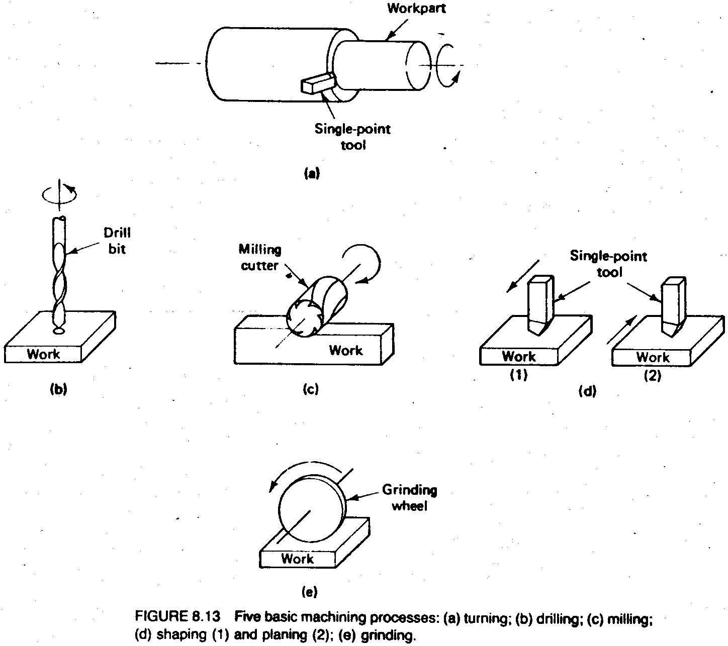
For each of the five machining processes, there are certain parameters, called cutting conditions, that are used to control the process and to achieve the desired results. These parameters are typically called the speed, feed, and depth of cut. (There is some variation in the terminology for the grinding process.) These cutting conditions are illustrated in Figure B.14 for a turning operation. The speed is the relative velocity of the tool with respect to the work surface. Units of surface feet per minute (sfpm) or meters per minute (m/min) are typically used to measure the cutting speed. For cutting tools that rotate, it is sometimes more convenient to refer to the rotational speed in rev/min. The feed is represented by the lateral displacement of the cutting tool relative to the work on catch pass or revolution of the tool. Typical units used are in./rev or in./pass. A related term applicable in most machining operations is feed rate, which is the lateral travel rate of the tool expressed in in./min. The depth of cut is the distance the tool penetrates below the original surface of the work, usually measured in units of inches or millimeters.
For milling and drilling it is often necessary to convert from surface speed to spindle rotation speed (and vice versa). Letting S represent the spindle speed in rev/min and V the cutting speed in sfpm,
![]() where D is the diameter of the cutter in inches. The same formula can be used to compute the spindle speed in a turning operation, given the surface speed, if we let D be the diameter of the cylindrical workpiece rather than the cutter.
where D is the diameter of the cutter in inches. The same formula can be used to compute the spindle speed in a turning operation, given the surface speed, if we let D be the diameter of the cylindrical workpiece rather than the cutter.
Also in a machining operation involving rotation (of the tool or work), feed expressed in in./rev might have to be converted to feed rate in inches per minute The conversion formula is
![]() where fr is the feed rate in in./min and f is the feed in in./rev. The feed rate corresponds to the travel rate used in Example 8.1, so we now see how the NC machine table travel rate is related to the machining operation,
where fr is the feed rate in in./min and f is the feed in in./rev. The feed rate corresponds to the travel rate used in Example 8.1, so we now see how the NC machine table travel rate is related to the machining operation,
 In a milling operation, the feed must sometimes be determined from the chip load on one tooth of the cutter. Suppose, for example, that a milling cutter has six teeth and each tooth cuts a 0.002-in.-wide chip on its travel into the work. This chip width taken by the milling cutter is called the chip load. The feed is determined as
![]() The three cutting conditions speed, feed, and depth determine the rate at which metal is removed during machining. This is called the metal removal rate (MRR) :
The three cutting conditions speed, feed, and depth determine the rate at which metal is removed during machining. This is called the metal removal rate (MRR) :
![]() where
where
V = cutting speed, sfpm
f = feed, in./rev
d = depth, in.
The factor 12 is used to convert the cutting speed from ft/min to in./min. Units of cubic inches per minute (in.3/min) are used for MRR.
Equation (8.12) is most applicable for a turning operation. For a milling or drilling operation some adjustments must be made. For example, for a drilling operation, MRR would most conveniently be calculated by multiplying the area of the drill by the feed rate (in./min). For a milling operation, the most convenient way to calculate MRR is by using the feed rate in in./min and multiplying by the cross-sectional area of the cut (depth x width).
The time required to accomplish the cutting operation is important in determining production rate. This is the time Tm referred to in Eq. (2.8). In most machining operations it can be determined from the formula
![]() where L is the length of the workpiece in the direction of feed travel. The value of L usually includes a small distance at the beginning and end of the cut to allow for over travel. This distance is small enough that it will be neglected in our calculations.
where L is the length of the workpiece in the direction of feed travel. The value of L usually includes a small distance at the beginning and end of the cut to allow for over travel. This distance is small enough that it will be neglected in our calculations.
With NC machine tools it is required that the MCU be capable of maintaining the desired cutting conditions in order to properly control the machining process. It is also necessary that the part programmer be sufficiently knowledgeable in these parameters to specify appropriate values for them in the program.
EXAMPLE 8.3
The cutting conditions for a turning operation performed on an NC machine tool are: cutting speed = 400 sfpm, feed = 0.010 in./rev, and depth = 0.100 in. The workpiece diameter = 3.00 in. and its length = 10.0 in. Determine the rotational speed, the feed rate, metal removal rate, and the time to travel from one end of the workpiece to the other.
Solution :
The rotational speed is given by Eq. (8.10) :
![]() The feed rate is given by Eq. (8.11),
The feed rate is given by Eq. (8.11),
![]() Metal removal rate can be calculated from Eq. (8.12) :
Metal removal rate can be calculated from Eq. (8.12) :
![]() Time to travel the 10-in, length can be determined from Eq. (8.13) by dividing the length by the feed rate :
Time to travel the 10-in, length can be determined from Eq. (8.13) by dividing the length by the feed rate :
 Machine tool technology for NC
Each of the five machining processes is carried out on a machine tool designed to perform that process. Turning is performed on a lathe, drilling is done on a drill press, milling on a milling machine, and so on. There are several different types of grinding operations with a corresponding variety of machines to perform them. Numerical control machine tools have been designed for nearly all of the machining processes. The list includes :
* Drill presses
* Milling machines, vertical spindle and horizontal spindle
* Turning machines, both horizontal axis and vertical axis
* Horizontal and vertical boring mills
* Profiling and contouring mills
* Surface grinders and cylindrical grinders
In addition to the machining process, NC machine tools have also been developed for other metal working processes. These machines include :
* Punch presses for sheet metal hole punching
* Presses for sheet metal bending
The introduction of numerical control has had a pronounced influence on the design and-operation of machine tools. One of the effects of NC has been that the proportion of time spent by the machine cutting metal under program control is significantly greater than with manually operated machines. This causes certain components, such as the spindle, drive gears, and feed screws, to wear more rapidly. These components must be designed to last longer on NC machines. Second, the addition of the electronic control unit has increased the cost of the machine, therefore requiring higher equipment utilization. Instead of running the machine on only one shift, which was the convention with manually operated machines, NC machines are often operated two or even three shifts to obtain the required payback. Also, the NC machines am designed to reduce the time consumed by the non processing elements in the operation cycle, such as loading and unloading the work part, and changing tools. Third, the increasing cost of labor has altered the relative roles of the operator and the machine tool. Consider the role of the human operator. Instead of being the highly skilled worker who controlled every aspect of the part production, the tasks of the operator have been reduced to part loading and unloading, tool changing, chip clearing, and the like. In this way, one operator can often run two or three automatic machines. The role and functions of the machine tool have also changed. NC machines are designed to be highly automatic and capable of combining several operations in one setup that formerly required several different machines. These changes are best exemplified by a new type of machine that did not exist prior to the advent and development of numerical control : the machining center.
The machining center, developed in the late 1950s, is a machine tool capable of performing several different machining operations on a work part in one setup under program control. The machining center is capable of milling, drilling, teaming, tapping, boring, facing, and similar operations. In addition, the features that typically characterize the NC machining center include the following :
* Automatic tool-changing capability. A variety of machining operations means that a variety of tools is required. The tools are contained on the machine in a tool magazine or drum. When a tool needs to be changed, the tool drum rotates to the proper position, and an automatic tool changing mechanism, operating under program control, exchanges the tool in the spindle and the tool in the drum.
* Automatic work part positioning. Most machining centers have the capability to rotate the job relative to the spindle, thereby permitting the cutting tool to access four surfaces of the part.
* Pallet shuttle. Another feature is that the machining center has two (or more) separate pallets that can be presented to the cutting tool. While machining is being performed with one pallet in position in front of the tool, the other pallet is in a safe location away from the spindle. In this way, the operator can be unloading the finished part from the prior cycle and fixturing the raw work part for the next cycle while machining is being performed on the current workpiece.
 Machining centers are classified as vertical or horizontal. The descriptor refers to the orientation of the machine tool spindle. A vertical machining center has its spindle on a vertical axis relative to the worktable, and a horizontal machining center has its spindle on a horizontal axis. This distinction generally results in a difference in the type of work that is performed on the machine. A vertical machining center is typically used for flat work that requires tool access from the top. A horizontal machining center is used for cube-shaped parts where tool access can best be achieved on the sides of the cube. An example of an NC horizontal machining center, capable of many of the features described above, is shown in Figure 8.15.
The success of the machining center has resulted in the development of similar machine tools for other metalworking processes. One example is the turning center, designed as a highly automated and versatile machine tool for performing turning, facing, drilling, threading, and related operations.
OTHER APPLICATIONS
The operating principle of numerical control. described in Section 8.1, is to control the relative position of a tool or other processing element with respect to the work. That same operating principle is applied to various other processes in addition to machining and press working. However, the applications are not always referred to by the term NC. Some of the machines and equipment utilizing NC-type controls include :
* Electrical wire-wrap machines. These machines, pioneered by Gardner Denver Corporation, are used to wrap and string wires on the back pins of electrical wiring boards to establish connections between components on the front of the board. The program of coordinate positions that define the back panel connections is determined from design data and fed to the win-wrap machine. This type of equipment has been used by computer firms and other companies representing the electronics industry.
* Component insertion machines. This equipment is used to position and insert components on an x–y plane, usually a flat board or panel. The program specifies the x– and y-axis positions in the plane where the components are to be located. Component insertion machines find extensive applications for inserting semiconductor chips (and other components) into printed circuit boards. They are also used for similar insertion-type assembly operations.
* Drafting machines. Automated drafting machines serve as one of the important output devices for a CAD/CAM (computer-aided design/computer aided manufacturing) system. The designs of a product and its components are developed on the CAD/CAM system, working through the various design iterations on the graphics monitor rather than on a mechanical drafting board. When the design is sufficiently finalized for presentation, the output is plotted on the drafting machine, basically a high-speed x–y plotter.
Coordinate measuring machines. A coordinate measuring machine (CMM) is an inspection machine used for measuring or checking dimensions on a part. The CMM has a probe that can be manipulated in three axes and identifies when contact is made against the part surface. The location of the probe tip is determined by the CMM control unit, thereby indicating some dimension on the part. Many coordinate measuring machines are programmed to perform automated inspections using NC. We will discuss the CMM in more detail in Chapter 18.
 * Flame cutting, plasma arc cutting, laser cutting, and similar machines. These are machine tools designed to achieve relative movement in two axes between a worktable and the cutting head (e.g., a gas or plasma arc torch or a laser beam) to perform cutting operations on plate and sheet metal. The cutting path typically involves curved and irregular outlines that cannot be accomplished economically on a conventional shearing press. Movement of the torch relative to the work is usually done by numerical controls. Figure 8.16 illustrates a laser cutting machine.
Additional applications of numerical control include tube bending, cloth cutting, knitting, riveting, and filament winding.
ECONOMICS OF NC
There are a number of reasons why NC systems are being adopted so widely by the metalworking industry. It has been estimated that 75% of manufacturing is carried out in lost sizes of 50 or less. As indicated above, these small lot sizes are the typical applications for NC. Following are the advantages of numerical control when it is utilized in these small production quantities :
1. Reduced non production time. Numerical control cannot change the basic metal-cutting process, but it can increase the proportion of time the machine is engaged in cutting metal, it accomplishes this decrease in nonproductive time by means of fewer setups, less setup time, reduced workpiece handling time, automatic tool changes on some machines, and so on.
2. Reduced fixturing. NC requires simpler fixtures because the positioning is done by the NC program rather than the fixture or jig.
3. Reduced lead time. Jobs can be set up more quickly with NC.
4. Greater manufacturing flexibility. NC adapts better to changes in jobs, production schedules, and so on.
5. Easier to accommodate engineering design changes on the workpiece. Instead of making alterations in a complex fixture, the program can be altered.
6. Improved accuracy and reduced human error. NC is ideal for complicated parts where the chances of human mistakes are high.
Where is NC most appropriate ?
It is clear from the advantages listed above that NC is appropriate only for certain parts, not all pans. The general characteristics of jobs for which NC is most appropriate are the following :
1. Parts are processed frequently and in small to medium lot sizes.
2. Part geometry is complex.
3. Close tolerances must be held on the work part.
4. Many operations must be performed on the past in its processing.
5. Much metal needs to be removed (for machining applications).
6. Engineering design changes are likely.
7. It is an expensive part where mistakes in processing would be costly.
8. Parts require 100% inspection.
 In order to justify that a job he processed by NC, it is not necessary that the job possess every one of these attributes. However, the more of these characteristics that are present, the more likely that the part is a good application for numerical control.
Economic analysis of an NC machine investment
There are two aspects of the economic analysis that will be discussed briefly here. The first deals with the introduction of numerical control into the plant. The second is concerned with the justification of a particular NC machine tool.
For an all-conventional machine shop deciding on the possible introduction of numerical control, the decision should be based on whether NC will meet the needs of the shop better than current methods. Determining how appropriate numerical control is for a given machine shop (or press working plant) should include consideration of the preceding list of job characteristics for which NC is appropriate. If the shop processes a high proportion and/or number of parts that fit these characteristics, then numerical control is suitable. Once the decision is made to proceed with NC, a substantial commitment is required by the company management. Introducing NC requires the training of machine operators, part programmers, computer specialists, maintenance personnel, and shop supervision. The involvement of nearly all shop personnel in some way or other is required to make the installation a success.
The second aspect of economic analysis deals with the justification of an individual NC machine tool. The methods for evaluating an investment proposal were presented in Chapter 3. Although different companies have their own ways of deciding on capital equipment proposals, the typical factors that should be included are presented in the NC machine economic analysis form presented in Figure 8.17. This form was based on information in references [ 2 ] and [ 4 ], as well as our discussion in Chapter 3.
